info@neofabacademy.com
+7 (727) 331 57 70
Mon–Fri, 09:00–18:00 (UTC+6)

From Code to Creation

Computer Numerical Control (CNC) machining represents the pinnacle of subtractive manufacturing — the art and science of removing material with precision to create functional parts. Unlike additive manufacturing, which builds objects layer by layer, CNC milling carves away material from solid blocks to reveal the desired form. This process offers unmatched accuracy, superior surface finishes, and the ability to work with a vast range of engineering materials.

At NeoFab Academy, we believe that understanding CNC machining is essential for modern engineers and makers. Whether you're prototyping a new product design, producing custom components, or studying the fundamentals of manufacturing, mastering CNC opens doors to transforming digital designs into physical reality with micron-level precision.

Fundamentals of CNC Operation
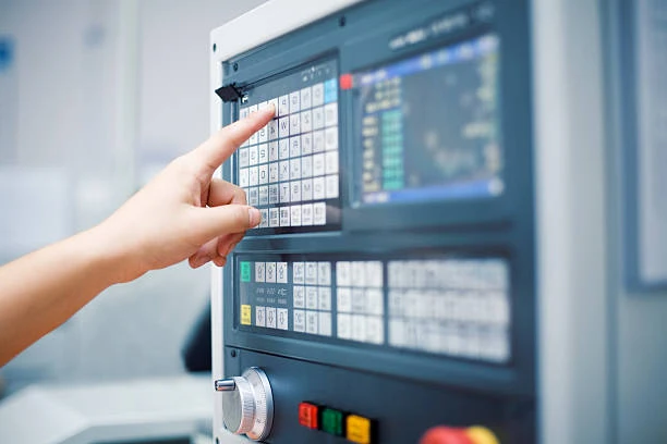
Control Systems

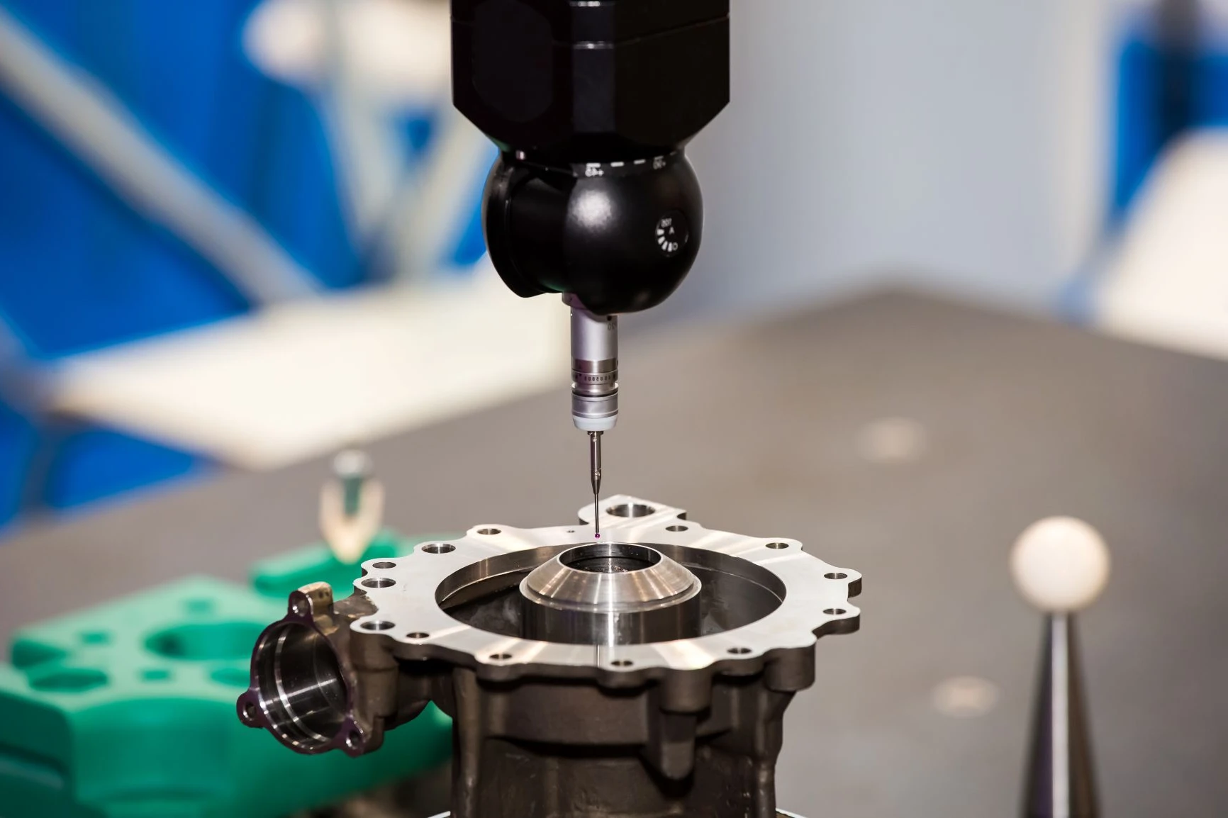
CNC machines interpret G-code instructions to coordinate multi-axis movements with sub-millimeter precision. Understanding coordinate systems, work offsets, and machine kinematics is fundamental to programming effective toolpaths.

Tooling Selection

Choosing the right cutting tool involves considering material properties, desired surface finish, cutting speeds, and feed rates. End mills, face mills, drills, and specialized tools each serve specific purposes in the machining process.

Cutting Parameters

Optimizing spindle speed, feed rate, and depth of cut directly impacts part quality, tool life, and production efficiency. These parameters must be calculated based on material hardness, tool geometry, and machine capabilities.

Understanding G-code: The Language of Machines

G-code serves as the universal language that CNC machines understand. Each line of G-code represents a specific instruction — moving the cutting tool to coordinates, changing spindle speed, selecting tools, or activating coolant systems. While modern CAM (Computer-Aided Manufacturing) software generates G-code automatically, understanding the underlying code enables troubleshooting, optimization, and creative problem-solving.

A typical G-code program contains several key elements:

  • G00 – Rapid Positioning: Moves the tool quickly to a position without cutting
  • G01 – Linear Interpolation: Cuts in a straight line at a specified feed rate
  • G02/G03 – Circular Interpolation: Creates arcs and circles
  • M-codes: Machine functions like spindle on/off, coolant, tool changes
  • F-code: Feed rate specification
  • S-code: Spindle speed in RPM

At NeoFab Academy, students progress from hand-writing simple G-code programs to using professional CAM software while maintaining a solid understanding of the underlying machine instructions.

CNC Machine Control Panel

Machine Coordinate Systems

Every CNC machine operates within a defined coordinate system. Understanding the relationship between machine coordinates, work coordinates, and tool offsets is crucial for accurate machining.

Machine Home Position: The absolute reference point (0,0,0) established during machine homing. All movements ultimately reference this position.

Work Coordinate System: A coordinate system defined relative to the workpiece, allowing programmers to define part geometry without knowing the exact machine position of the stock material.

Tool Length Offset: Compensates for different tool lengths, ensuring consistent Z-axis positioning regardless of which tool is loaded.

Properly setting up coordinate systems prevents crashes, ensures dimensional accuracy, and simplifies programming for complex multi-setup operations.

Material Behavior in Machining

Different materials respond uniquely to cutting forces, heat, and tool contact. A machining strategy optimized for aluminum will fail catastrophically when applied to hardened steel. Understanding material properties — hardness, ductility, thermal conductivity, and chip formation characteristics — is essential for successful CNC operations.

Aluminum Alloys

Characteristics: Excellent machinability, high thermal conductivity, prone to chip welding

Challenges: Built-up edge formation, chip evacuation in deep pockets

Strategy: High cutting speeds, sharp tools, generous chip clearance, minimal coolant to prevent chip re-cutting

Stainless Steel

Characteristics: Work-hardening behavior, lower thermal conductivity, high strength

Challenges: Tool wear, heat accumulation, surface hardening during cutting

Strategy: Moderate speeds, higher feed rates, positive rake angles, abundant coolant application

Engineering Plastics

Characteristics: Low melting point, flexible, varying hardness

Challenges: Heat-induced deformation, material melting, poor dimensional stability

Strategy: Sharp tools, low cutting temperatures, air cooling, support for thin sections

Tool Steels

Characteristics: High hardness, abrasive, excellent strength

Challenges: Extreme tool wear, high cutting forces, precise tolerance requirements

Strategy: Carbide or ceramic tooling, lower speeds, rigid setup, high-pressure coolant

Research Focus: Machining Science

Recent studies at Nazarbayev University's Engineering School investigate the relationship between cutting parameters and surface integrity in titanium alloys — materials critical for aerospace and medical applications. Their research demonstrates that tool path strategies significantly impact residual stress patterns, which directly affect part fatigue life. This work exemplifies how academic research continues advancing manufacturing knowledge.

Chip Formation and Control

Chip formation is a complex phenomenon involving plastic deformation, shear, and fracture. The type of chip produced — continuous, discontinuous, or segmented — reveals important information about the cutting process and helps diagnose problems.

Continuous Chips: Long, unbroken ribbons indicating ductile material and stable cutting conditions. Ideal for most operations but requires proper chip breaking to prevent tangling.

Discontinuous Chips: Short, separated segments typical of brittle materials or interrupted cuts. Easier to evacuate but may indicate tool chatter or poor surface finish.

Built-Up Edge: Material adhering to the tool cutting edge, disrupting cutting geometry. Results from excessive heat or inadequate cutting speeds. Prevented through proper speed selection and coolant application.

Effective chip control involves selecting appropriate chip breaker geometries, optimizing feed rates, and ensuring adequate coolant delivery to the cutting zone.

Academic Insights into Precision Manufacturing

The Quest for Micron-Level Accuracy

Precision manufacturing demands controlling every variable that affects dimensional accuracy: thermal expansion, machine deflection, tool wear, and vibration. Academic research continuously pushes the boundaries of what's achievable in CNC machining.

Temperature effects alone can cause dimensional variations of 10-50 microns in typical machining operations. Modern research focuses on predictive compensation — using real-time temperature monitoring and mathematical models to adjust toolpaths dynamically, maintaining tolerance even as thermal conditions change.

Machine tool stiffness determines resistance to cutting forces. Finite element analysis now enables engineers to optimize machine structure before physical prototypes exist, reducing weight while maintaining rigidity. This research directly impacts machine design and performance.

Precision Measurement Equipment
5
μm
Typical CNC Accuracy
1
μm
High-Precision Machining
1
μm
Ultra-Precision Level
50
nm
Research Frontier

Five-Axis Machining: Complexity and Capability

Traditional three-axis CNC machines move along X, Y, and Z axes. Five-axis machines add two rotational degrees of freedom, enabling the cutting tool to approach the workpiece from virtually any angle. This capability revolutionizes manufacturing for complex geometries like turbine blades, medical implants, and aerospace components.

However, five-axis machining introduces significant complexity. Tool collision avoidance requires sophisticated simulation software. Coordinating five simultaneous movements demands advanced control algorithms. Post-processing software must translate CAM toolpaths into machine-specific G-code that accounts for machine kinematics and safety limits.

Research at institutions like ETH Zurich focuses on optimizing five-axis toolpaths to minimize machining time while maintaining surface quality. Their work on simultaneous five-axis roughing strategies has reduced machining times by 30-40% for complex parts compared to conventional 3+2 axis approaches.

Educational Philosophy

NeoFab Academy emphasizes both theoretical understanding and practical skills. Students don't just learn to press buttons — they understand why certain parameters produce better results, how to diagnose problems when things go wrong, and how to optimize processes for efficiency and quality. This deep knowledge distinguishes truly skilled machinists from button-pushers.

Adaptive Machining and Smart Manufacturing

The future of CNC machining lies in adaptive, intelligent systems that respond to real-time conditions. Sensor integration enables machines to detect tool wear, vibration, and process anomalies, adjusting parameters automatically to maintain quality.

Force sensors measure cutting loads, enabling adaptive feed rate control that maximizes material removal while preventing tool breakage. Acoustic emission sensors detect the ultrasonic signals generated during cutting, providing early warning of tool wear or chatter onset. Thermal cameras monitor temperature distribution, triggering coolant adjustments or speed modifications to maintain dimensional accuracy.

Machine learning algorithms trained on historical machining data can now predict optimal cutting parameters for novel material-tool combinations, reducing the trial-and-error typically required when machining unfamiliar materials. This represents a paradigm shift from purely experience-based machining knowledge to data-driven optimization.

Vision Systems

In-process measurement using machine vision enables real-time quality verification and adaptive toolpath correction without removing parts from the machine.

Vibration Analysis

Frequency domain analysis of vibration signatures identifies chatter conditions before they degrade surface finish, enabling automatic parameter adjustment.

Digital Twins

Virtual replicas of physical machines enable simulation-based optimization and predictive maintenance, reducing downtime and improving productivity.